Stabilizers are used to keep heavy moving parts in a fixed or relatively fixed position. For example, it can fix the position of an underarm of a human figure MOC, but still allow it to be set in different positions. This article introduces a basic design of a stabilizer and things to consider when one designs one for a practical application.
Introduction
The Troll mk II, that I am busy designing should have moveable arms and other body parts. However, it seems to become quite a big MOC, so regular hinges like pins and ball joints, will not work because they are too small, and provide too little friction to hold things in place. As it happened, I recently ran into Stevil9‘s MOC Sabre-wolf design – a great alt build for the McLaren Senna GTR.
If one looks at the Sabre-Wolf’s hind legs, one can see yellow axles sticking out. They are there to keep the ankle joints from caving in under the weight of the animal, but they still allows one to give the ankles different angles and position the legs of the MOC. Inspired by this example, I started tinkering and experimenting because I believe there is great potential for applications.
Great potential for applications
The stabilizers can be applied in limbs of robots, animal and humanoid figures, as many of Stevil9‘s MOCs are showing. I am also imagining applications in spines for animal and humanoid figures, flexible towers, and highly curvy designs of snakes and dragons. They can increase play-ability and display value. As I found out, when well designed, the stabilizers can take quite heavy loads, so they could be applied in big and complex MOCs.
Our favorite toy maker also feels it has great potential, considering that since 2024, there are ready-made stabilizers consisting of this part and this one. They are used in set 60420-1 Yellow Construction Excavator. I am however interested in a stronger version, with more resistance, and an adaptable design.
Basic design
Here is a basic demonstration design:
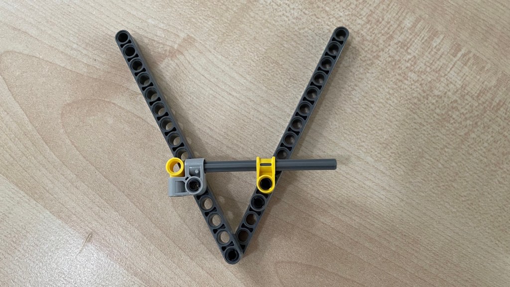
There are two liftarms ( which I will also call ‘main arms’ ) which can hinge around the main hinge at the bottom. Somewhat away from the main hinge, there is an axle that is attached so that it also hinges with both liftarms. On one end ( in the picture above left ) the axle is fixed to the light grey hinge brick. Let’s call this the hinge block. One the other end, the axle can slide through the yellow connector brick. Let’s call it the friction block. The axle can slide through the block, but there is quite some friction between the two, which does the actual work of stabilizing the main arms in the angle that they are set.
Try it out, but don’t implement this as it is because there are a few problems to solve and options to choose, which are discussed in the following sections.
Length of the axle
Depending on how much the two liftarms should be able to hinge, the axle may slide out of the yellow connector brick. This is easy to see. If the two liftarms were to change their angle to 180 degrees, the axle would pop out, long before they would reach that.
There are a couple of possible solutions. One would be to move the hinge points of the axle closer to the hinge point of the liftarms. This can be done but has the downside that the stabilizer will work less well. In case of the Sabre-wolf, the ankles may buckle in spite of stabilizer. For the same stabilizing effect, one would need more friction. ( see below)
Another solution is to use a longer axle. However, the choice is limited. More about that in the next section about the connector block. Another problem with using a longer axle is that when one changes the angle of the liftarms, this causes quite some strain on the axle because of the friction with the friction block. So much so, in fact, that the axle bends a little bit. I think that is acceptable, but with longer axles it could be problematic. They might even fold or break. So, longer axles would not be preferable, and one would need to extend the axle with a liftarm, which will be discussed in the next section.
The third solution is to prevent the arms from bending that far. Of course this may not be desired, but it is an option. Let’s now look at the connector block.
Connector block
The connector block makes sure that the axle does not slide on two of its ends. For this, it is important that it holds the axle in place both when the axle is being pulled ( that is, when the liftarms are being opened ), and when it is being pushed ( when the liftarms are being closed ).
There is a ready-made part, introduced in 2024, consisting of a 3L axle with a pin hole at one end. It is exactly what is needed and nothing more. Unfortunately, at the time of writing ( June 2024 ), there is only the 3L version.
Other than this ready-made part, the best solution for a connector block that I can think of, is to use an axle with a stop. At present, this limits the choice to axles of 3, 4, 5, 5.5 ( or this version ), or 8 units long. There are no longer versions, but maybe that is for the best because they might be too long, as explained above.
The most compact design that I can think of, is the connector block in the picture above. I never could find a good use for the light ( bluish ) grey pin connector with the perpendicular bent, but here it is. Slide the axle in one of the perpendicular pin holes until the stop, and lock it in place with the yellow pin with pin hole ( or this version ). One could use something else to block the axle, but this choice has the advantage that the connector has two choices for a hinge point on the liftarm.
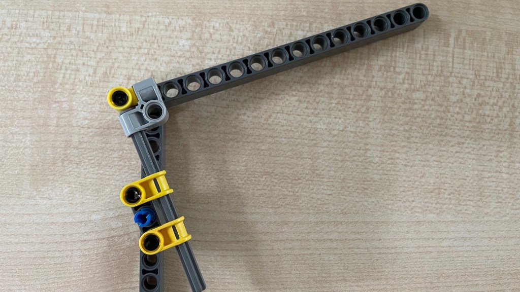
If the axle is too short, it can be extended with a liftarm. One concern is that the axle should not hinge with that liftarm and that the connection is really strong. See the picture below for a solution. The liftarm is rather short, but it could be longer of course. This, 3 units, would be the minimum length.

If one inserts the 5.5L axle with the stop between the two pin-with-pin-hole parts (obviously one needs to do that before inserting them in the liftarm), the axle won’t hinge with the liftarm and it is done. If one would do the same with the 8L axle, which has the stop at its very end, it will likely hinge with the liftarm when it is under pressure. If one inserts it so that the stop is at the top of the two pin-with-pin-hole parts, it won’t hinge but it will slide out. So one would still need to replace the black pin with something else. For example a blue 3L pin and a 1 x 1 liftarm.
A final note on the connector block design. A good look at Stevil9’s MOCs shows that other solutions are possible. In the photos of the Battle Mech one can see the stabilizer for the knee joints use friction instead of stop-based connector blocks. The connector block simply has more friction ( by adding bushes in this case ) than the friction block. It works, but it depends on the quality of the bricks used.
Now it is time to examine the friction block, which does the actual work.
Friction block and stabilizing effect
In the picture at the top, the friction block is simply one axle-and-pin-connector-perpendicular with a pin to attach it to the liftarm. This connector gives quite a lot of friction, perhaps even an ideal amount for many uses. One can however increase the amount of friction, for example by adding a axle-pin-connector-perpendicular-double-split. Like the orange one in the picture below.
It is very easy to build and has the feature that one can attach other bricks to it.
Another way to increase the friction is to simply line up more of the yellow connectors. Like in the picture below.
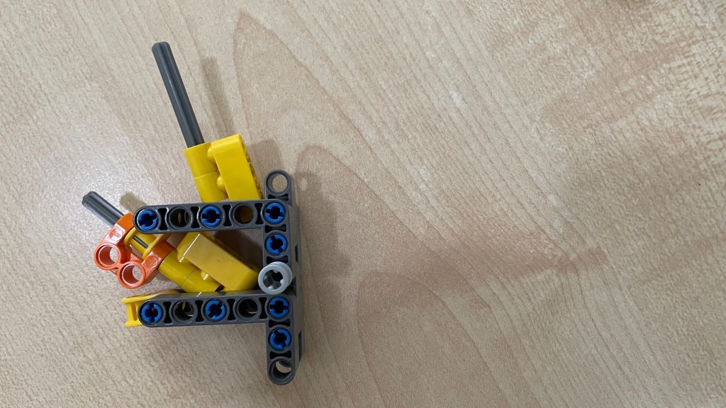
This solution provides so much friction that opening and closing the main arms five times make the hinge pins, or the parts connected to them, pop out! As one can see in the next picture.

One would need more robust designs of the connections between the different parts. For example like this …


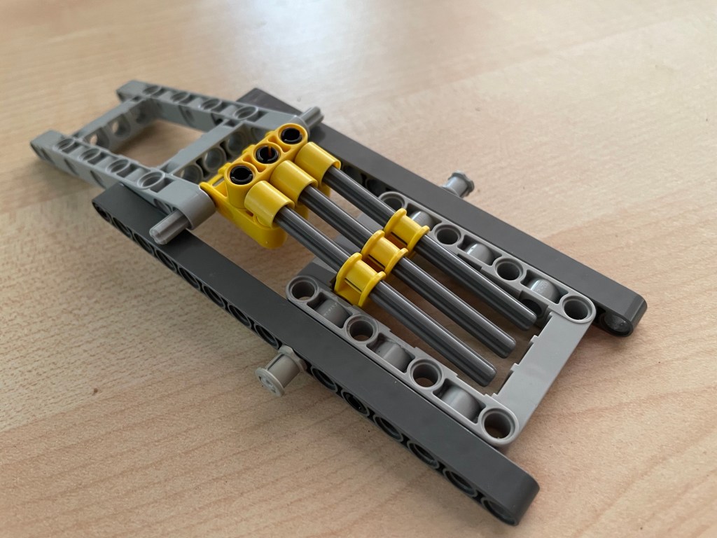
Here are three 8L axles with three friction blocks, but because of the double liftarms and the use of frames, the hinges don’t pop after repeated use. Some experimentation would be needed to find out the level of reinforcements needed.
A side note : One downside of this more robust design is that the two main arms can not hinge less than about 90 degrees. With smaller angles the axles pop out of their respective friction blocks.
Playing around with different parts and amounts, one can likely reach the friction necessary for the stabilizer’s intended use. More friction is possible, as illustrated, but less friction may be possible too. Frankly speaking, I haven’t tested this. I tried the half-bush but that one provides more friction than the axle-and-pin-connector-perpendicular.
It is good to keep in mind that once a choice for the design of a friction block is settled, its stabilizing effect is not the same. This is the topic of the next section.
Same friction but different stabilizing effect
Besides the amount of friction that a friction block generates, there are two, or at least two, factors that influence it’s stabilizing effect.
Firstly, the location of the connector block and the friction block on their respective main arms influences the stabilizing effect. Moving either one or both closer to the main hinge reduces the stabilizing effect, and moving them further away has the opposite effect.
Secondly, given fixed positions of the connector block and the friction block on their respective main arms, the stabilizing effect differs, depending on the angle between the main arms. If these arms are at a 90 degree angle, the effect is bigger ( i.e. it takes more force to change the angle ) than when the arms are at 180 degrees or 0 degrees. The point to remember is that even though the amount friction does not change, the stabilizing quality is not constant or linear, but sinusoidal.
Conclusion
This article introduces the potential applicability and basic design of a stabilizer. For as far as I am aware of them, the article also explains the essential parts and considerations when one designs a stabilizer for a practical application in a MOC. Clearly, there are limitations to take into account, but they open a world of possibilities for MOC designs.
Please do leave comments and suggestions!
June 2024
