
.
.
This summer I created a series of ‘spines’ to demonstrate the use of friction stabilizers. I uploaded three varieties ( spine, ‘snake spine‘ and a ‘fish spine‘ ) which have different qualities, but all three bend only in one direction. This is obviously a limitation compared to most real spines which also bend orthogonal to their main bending direction. A human spine bends mostly forward and backward, but also side ways to some extent. Also snake or fish spines bend mostly sideways, but also a little or a lot upwards. So, would it be possible to make a dragon spine, which can bend equally well in two direction, like a Chinese dragon?
Obviously, yes, as one can see in the pictures on this page. I have made different designs, and made building instructions for one of them. Do note that these are proof-of-concept designs, which will need further modifications to be used in other MOCs.


There were a and are a few problems to overcome.
Firstly, instead of a pin-based-hinge, two vertebra need to be separated by a ball joint. This is possible but unfortunately there is no brick that consists of a short bar with a ball on one side and a ball joint on the other. So separate pieces ( such as ball and joint , alternative versions exist ) are needed for that.
Secondly, because each set of vertebra has two sliders and friction blocks, which create twice as much resistance compared with the earlier designs. So, the construction needs to be strong to keep all forces in check.
Unfortunately, the ball joints have no easy attachment holes to provide a strong connection with the rest. It is possible, but requires some fidgeting.
The v1 and v2 are the simplest but because the crossing bars are separated with one stud/hole in between, bending forward and sideways are not symmetrical. This may ( or may not ) cause problems with final MOCs in which the designs are used.
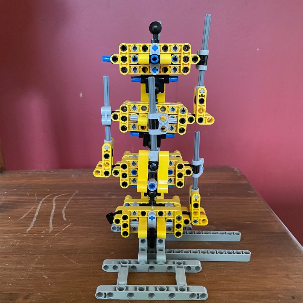
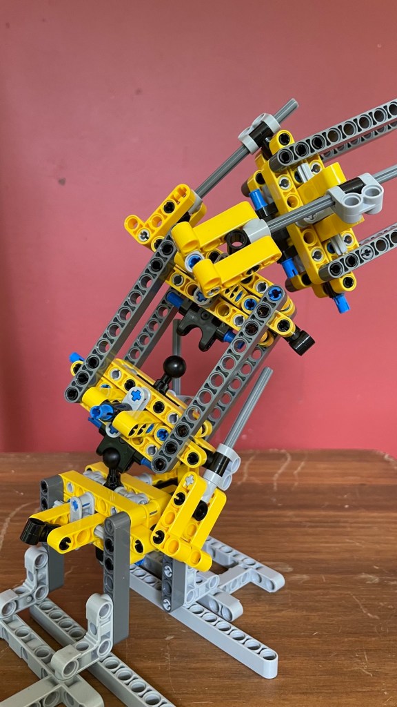
V3 overcomes this problem. I have tried to make it as compact as possible but the vertebra is still 9 studs/holes across. And the distance between the ball and the ball joint is 5 studs/holes.
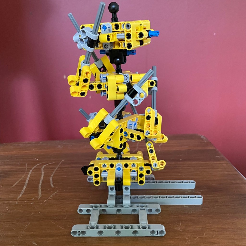
The short distance between the ball and the ball joint is actually too short. As the pictures below show, a spine made out of these vertebra can not bend a lot in either direction. The slider axles soon hit the next vertebra.

.
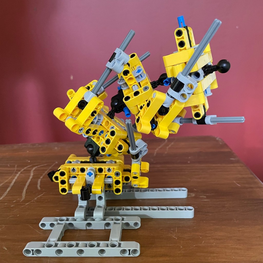
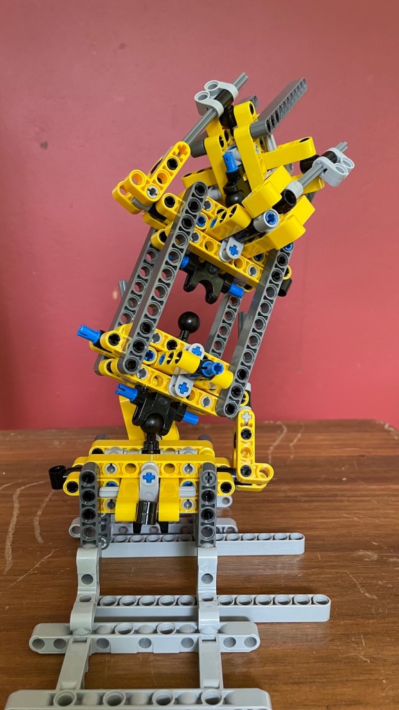
As shown in the pictures below, the spine can bend a bit further by twisting the vertebra relative to each other. This causes the sliders to move sideways, but they will still easily get entangled.

.
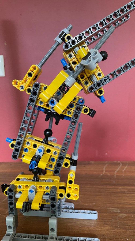
So, an improvement of the design would be to increase the height of the vertebra. This is provisionally done with v3 vertebra in the pictures below. Note that here hare only three vertebra, not 4.

.
The design can be improved now because the ball and the ball joint can be attached to different parts. This allows the use of a different ball joint, such as 61053 or 50898. An additional advantage of making ‘higher’ vertebra is that they offer more opportunities to connect the spine to a bigger MOC.
31 December 2024
