MOC manual service. Get a step-by-step manual of your MOC.
Click here to learn more.
1 Recap
You can skip this if you have read the previous posts.
Five weeks ago, I started making an alternative build ( alt build ) for the VTOL Heavy cargo spaceship LT81 ( in this post, I refer to it as the original set ), and I decided to explain how I think making an alt build starts. It maybe helpful for those who do not know how to start, and it helps me reflecting on how I work and hopefully improve, perhaps with your comments.
The posts are structured in chapters and sections in such a way that you can easily follow the steps and the thinking even if you are not interested in Technic or spaceships. The spaceship is just the example. You can read all about that in these five posts:
- Introduction to three steps
- Sketching a first design
- Running into a snag with an essential feature
- Pivoting
- Moving on after pivoting
At the end of the fifth post, I concluded, that ‘yes’, my idea will most probably fly.
Below you see the various overall sketch versions. To get to the last version, I had to do some rethinking of what I wanted to build, which essential features is has, and how the spaceship should be operating. I realized that one really needs flexibility in thinking.
All images in this post can be clicked for a full screen version
After this rethinking, the idea for the spaceship is that 1) it has a more symmetrical and realistic design compared to the original set. Initially, I was toying around with both a three and four engine version, but I traveled down the four engine path. 2) Instead of hanging the cargo under the ship, it should be held inside the ship during flight. 3) The ship should have some folding mechanism for landing and takeoff, i.e. the engines have to move away from and back to the ship’s hull as illustrated in v3.
So, I finished the blog series of how to get started on an alternate build. Since there was quite some interest among Rebrickable and Reddit users, and because the writing keeps helping me improving my skills, I am continuing the series with some more insights and reflections on how I design MOCs and alternate builds.
As before, I aim to write in general about the design of an alternate build and use the spaceship as an example. If you are only interested in the design insights, then know that the following chapters have two sections. The chapter title announces the design insight, the A section tells about the development of the spaceship, and the B sections ( aptly called ‘MOC design’ ) provide the insights. Here is a clickable table of contents.
- 1 Recap
- 2 Incremental design
- 3 Do not always implement every detail. Save it for later.
- 4 Seemingly small changes may cascade through the design
- 5 Setting bricks aside
- 6 Structural integrity
- 7 Vicious spiral of finding alternative solutions
- 8 Version 4
2 Incremental design
2A First implementation of the folding mechanism
After I tinkered together a concept folding mechanism and a way to power it and after I concluded that I probably have enough bricks for it, the next step would be to put my money where my mouth is and implement it fourfold in the sketch design of the ship. More importantly, that mechanism would be close to the heart of the ship, so it should be made first before adding other features and details. Adding it towards the end of the process would generate endless adaptation of the other features.
Unfortunately, two weeks passed between the building and the writing of this post, so I can not remember anymore all the details and reasons, but I can reconstruct some, based on the photos that I took.
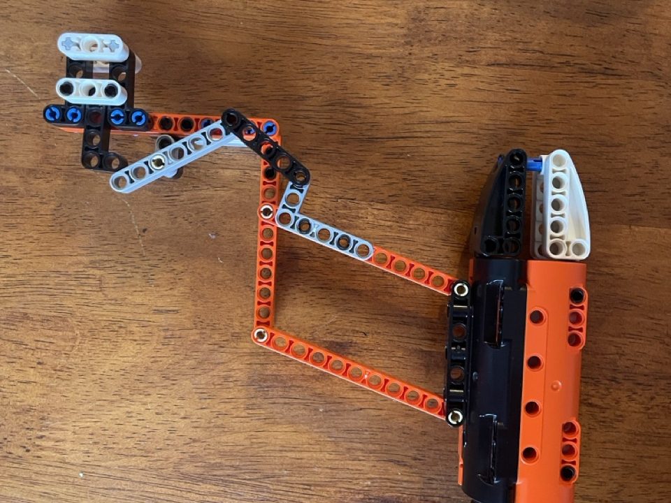
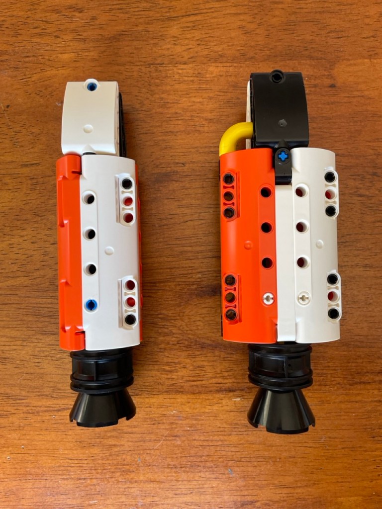
Here is the basic mechanism that I designed ( left ) and what must have been the first implementation of the folding mechanism on only one engine pod.
2B MOC design
Notice that I started working on an important feature simply by doing. There was no master plan of how to go about it. I just reasoned my way to the next step. And then the next and so on. It works and has its advantages and disadvantages, as will become clear in this post and others.
However, it is not the only way to proceed. Another one, on the other side of the spectrum ( if there were such a thing ) would be to first plan the entire MOC at a much greater level of detail than the sketches that I have been showing so far. Then make a plan and then execute that plan, and adjust it on the way. This also has its advantages and disadvantages.
I am no expert in design processes, but my guess would be that the bigger the MOC, the more likely the plan-all-in-advance approach would work best. What constitutes a ‘big MOC’ is a subjective matter, in part depending on the experience of the designer.
3 Do not always implement every detail. Save it for later.
3A Additional support
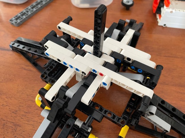
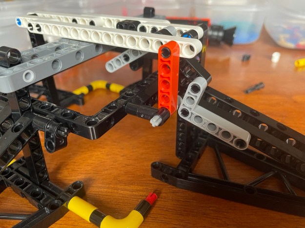
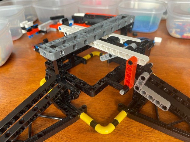
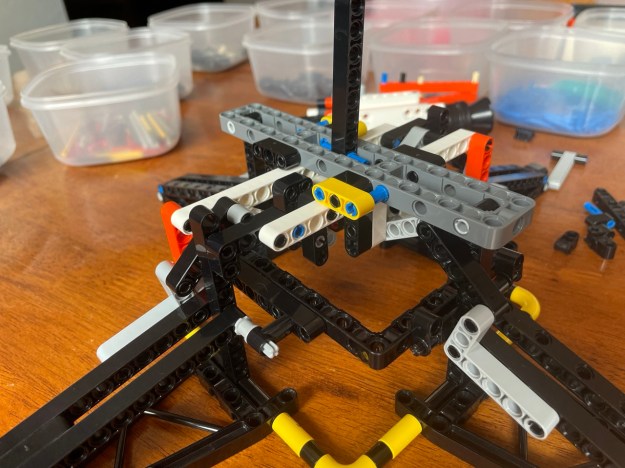
Next, I added additional white bars for extra support. See the picture below. The sharp observer will notice that these bars do not add any support at all. For that to happen, the black pin at the top of the orange 5 stud bar and the blue pin that is in the same line need to be replaced by an axis ( or so ). But I think I considered it too much work for the time being and that I could more easily do it in the course of later, more radical redesign.
3B MOC design
When working on a design in such a hands-on and incremental way, it may be a waste of time to implement an improvement or new idea in full. The reason is that it may have to be changed later on, moved to a different location in the MOC, or removed completely. My advice: implement it well enough to see what it will amount to visually and structurally. Make a mental note of all that you still want to do on the implementation and move on. Over time you will get better at remembering, but the list may get too long. Then make an actual note on paper, in an app, or text file, or whatever has your preference.
4 Seemingly small changes may cascade through the design
4A Moving the grey frame to the top
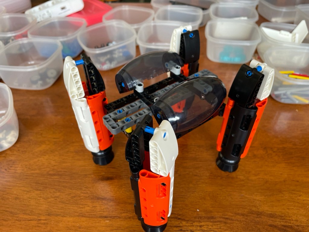
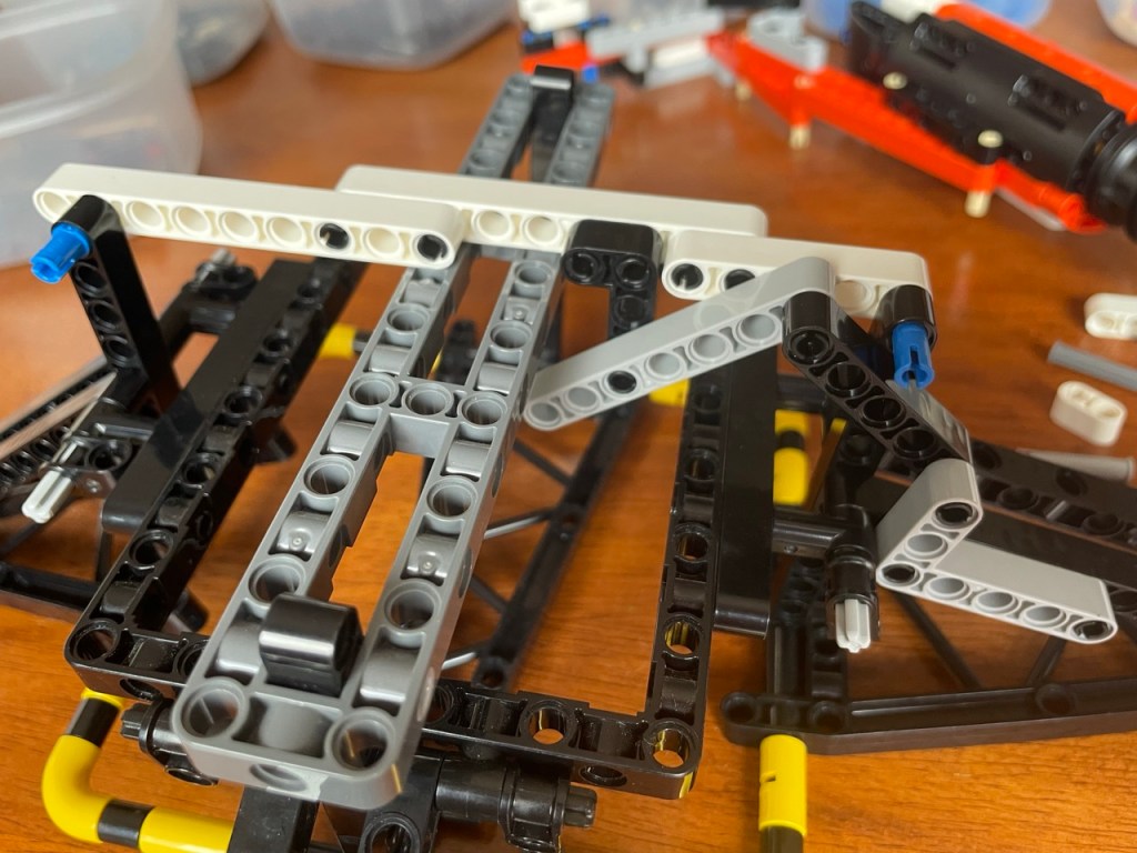
Assuming but also checking brick counts to make sure that I can make the exact same mechanism on the opposite side of the spaceship, I turned my attention to adding the folding mechanism to the arms attached to the grey frame. If I remember correctly, it was only then that I realized that that frame is below the white bars and that the mechanism would not fit. It would have to move upward one pinhole in one place ( sorry, that is a bit vague, but it would be too complicated to explain and not really necessary ). This meant – apparently, at least to me, at that time – that the grey frame should be on top of the white bars because the mechanism could move downward one pinhole. The following picture shows the result.
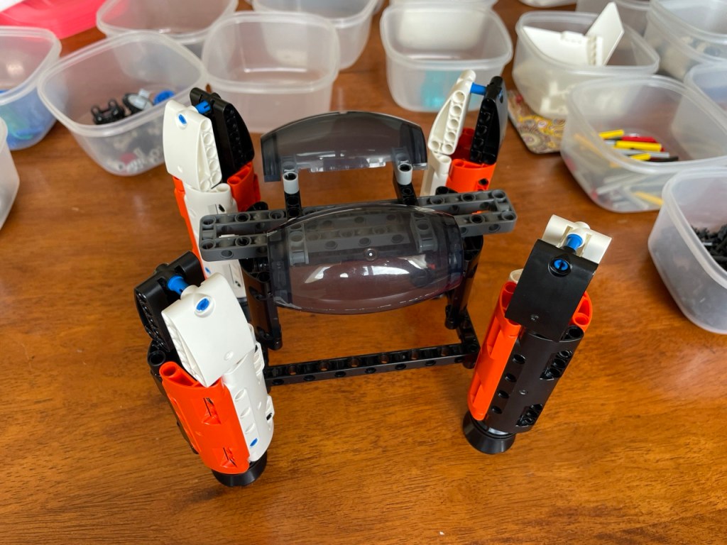
While writing, I notice that in the picture below, the system of white bars is changed and now includes not one but two 15 stud bars. Unfortunately, I do not remember why I made that change.
The above looks simple, right? Except that the distance between the white bars and the black frame remains the same ( notice the vertical orange bar ). For that to be possible, I had to move the frame including the long bars leading to the engine pod, one stud down. That was a lot of work. Doable. But a lot.
Changing the distance between the white bars and the black frame had another consequence, which I will deal with in the next chapter. But first:
4B MOC design
Moving bricks just one stud, pin hole, or plate in one place, may have tremendous consequences. Directly, and as will become clear in the next section, indirectly. There can be an avalanche of consequences, or, less dramatically, a cascade or ripple effect throughout the design. Seeing all these consequences in advance, especially in MOCs that outsize one’s experience or skill level, can be very difficult.
One measure to counter the effect is modular design: design the MOC in different sub-models or sub-designs with relatively simple connections between them. Much can change in the sub-models, but as long as the bricks that constitute the connection remain the same and in their relative position, the ripple effect may remain limited to the sub-model. However, never say never. There always is the possibility that the ripple effect does cause changes in adjacent sub-models.
Sometimes, when shifting a lot of bricks is necessary, it can become difficult to keep track of all bricks and their previous and new position in the design. In that case, instead of changing the existing design, one can also keep that version and build a copy with the shifted design from scratch. For this, one does need to have the bricks to do so. If those are not available, then another option is to first make a digital version of new design, and only then making the changes to the existing MOC.
5 Setting bricks aside
5A New engine pod designs
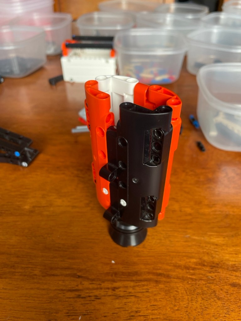
Lengthening the distance between the white bars and the black frame, meant that the vertical distance between the two arms that hold an engine pod also changed. It became one stud shorter. This meant that the connections between these arms and the engine pod could not be made in the same way. Which meant redesigning the pod.
There was a second reason for redesigning the pod, which is one of the things I had postponed ( as in chapter 3 of this post ) when I first connected the pods to their arms. The connections were made with pin with pin-hole bricks. They have the downside that the pins can turn around their axis, which made the connections between the arms and the engine pod rather shaky. The pod would not remain entirely straight but could twist somewhat. Instead of the pin with pin-hole bricks, I wanted to use 2×4 L-shaped bars.
I tried out various other designs for the engine pods, of which I unfortunately did not take any pictures, and ended up with flat versions. As in the following pictures.
There were other changes that I wanted to make to the folding mechanism, so I did not immediately build all four engine pods.
5B MOC design
This is just a simple work tip for developing an alternate build. Sometimes, you know you are going to build one or more sub-models of you MOC, but you postpone it to later. To make sure that you do not use bricks that are already reserved, just set them aside in a separate heap or bin. You want to stay within the brick set of the original set, so you can not afford to use a brick more often than there are copies in the original set
6 Structural integrity
6A The first test of the folding mechanism
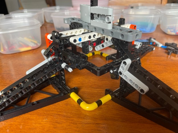
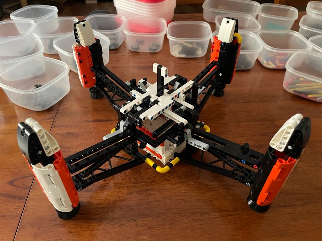
After exchanging the positions of the grey frame and the white bars, implementing the folding mechanisms on the grey frame appeared very easy. I then built the folding mechanism on the two remaining sides. I also created a ‘plunger’, the thing that the user/player has to push down to drive the folding out of the arms. The mechanism started to come together, as the next photo shows.
I could then do a test drive of the mechanism. It failed spectacularly. Driving an engine pod arm puts so much pressure on one of the hinge points that the L bar holding it would bend away. Beginners mistake and easy to solve. So version 2 of the folding mechanism looked like this.
The grey frame and the white bars also needed to be bolted together for the entire spaceship frame to hold together when pushing the plunger down. I did that but do not have a picture.
6B MOC design
In Technic MOC design but also when working with system bricks, structural integrity is a real thing. Official LEGO sets tend to be massive assemblies, dense with layers and layers of bricks, and with all kinds of reinforcements wherever possible. I think it is because of this: nobody who plays with or just handles a model wants it to fall apart while holding it. Or at all, actually. And even if it does not fall apart, nobody is happy with even just a little shaky end result. So, it pays off to invest a lot of effort in giving your MOC a lot of so-called structural integrity: whatever you do, make it strong.
7 Vicious spiral of finding alternative solutions
7A Replacing the grey frame
The grey frame has been part of the sketch design from the beginning, but it hinders the movement of the folding mechanism. As you can see in the photo above, the grey frame prevents the left/top side of the black bar that is attached to the grey 5×3 L-shaped bar to move further up. At the same time the arm to which the L-shaped bar is connected, is still pointing downwards, whereas the idea/plan is to have it hinge completely horizontal.
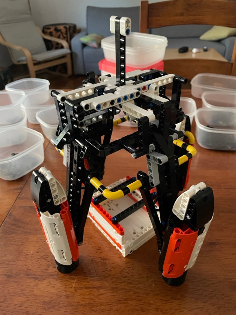
However, to replace the grey frame with two 15 stud white bars was not possible because the original set only has two 15 stud bars in white, and all other colors for that length have been used. So, I had to redesign the system of white bars. The picture below shows the result.

Notice, that in the middle, I also added some small bricks to hold the plunger in place. More importantly, notice that I had to use three bars to replace the one of 15 studs. That brings me to the point of this section:
7B MOC design
When you work with a limited set of bricks, either because you do not want to buy more or you are making an alternate build, at some point you will have to start improvising. That is, you will have to build structures with what you have rather than with better suitable bricks that you know exist. In principle, it means that you will use more bricks, rather than fewer. You are then entering a vicious spiral of finding alternatives for bricks that you already used for another alternative construct.
It is not always that bad. Sometimes you are lucky and you are able to simplify or redesign at a later point. Or the alternative design introduces lucky additional options to build or connect other features to your design.
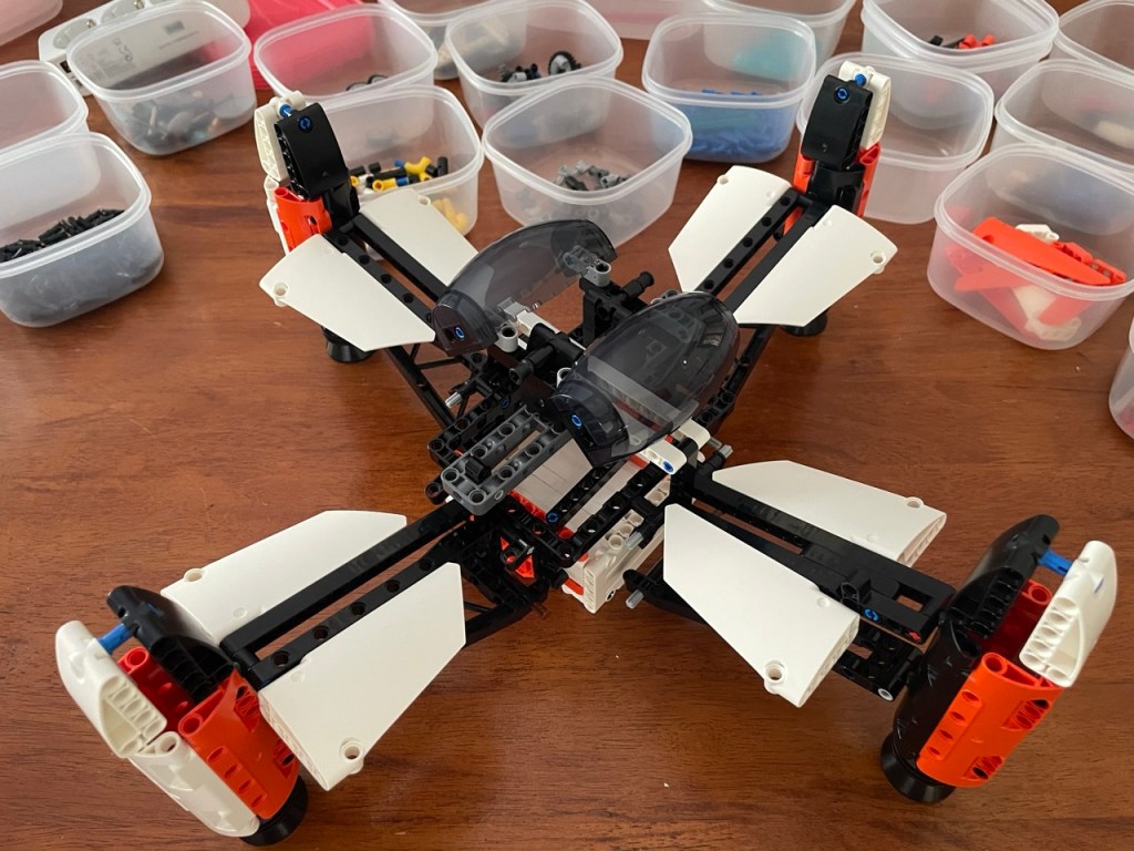
8 Version 4
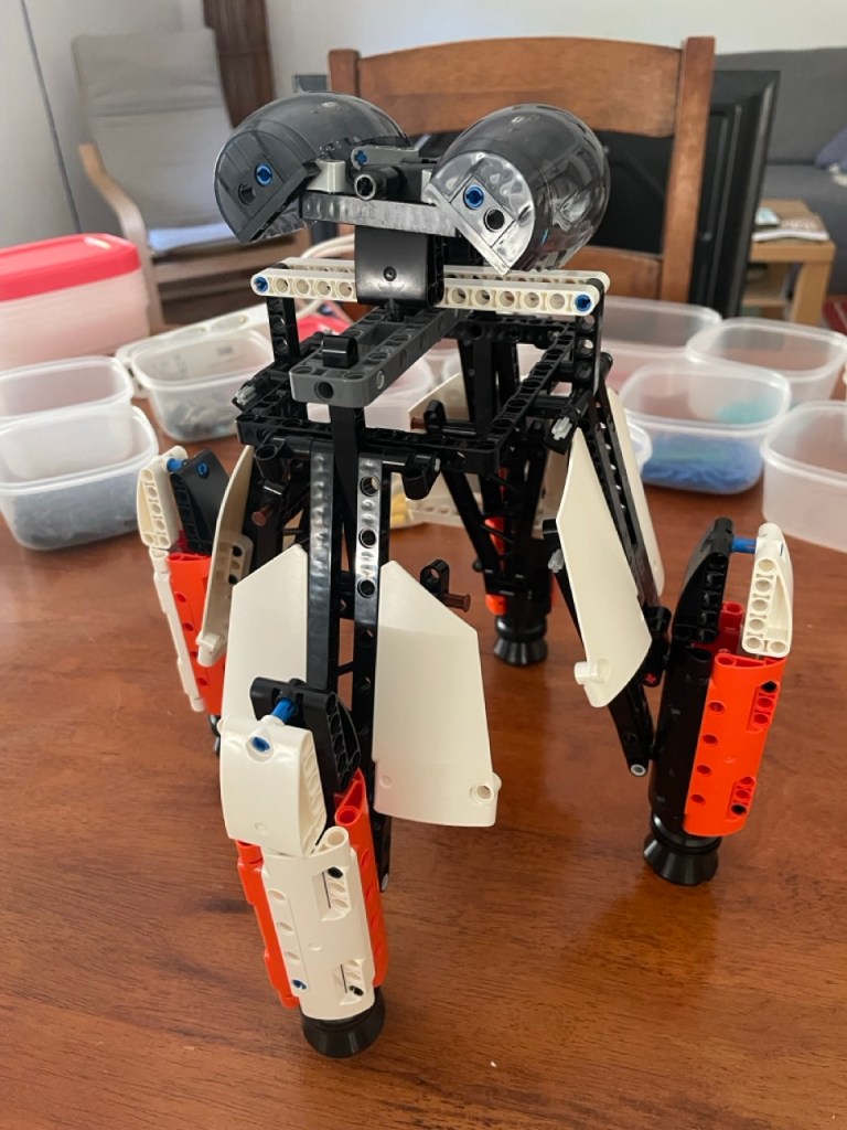
The folding mechanism is not yet finished. It still needs a decent block so that it does not lower the ship too much, but it is still nice to occasionally assemble the entire MOC to see the progress, and to see if you have not overlooked something.
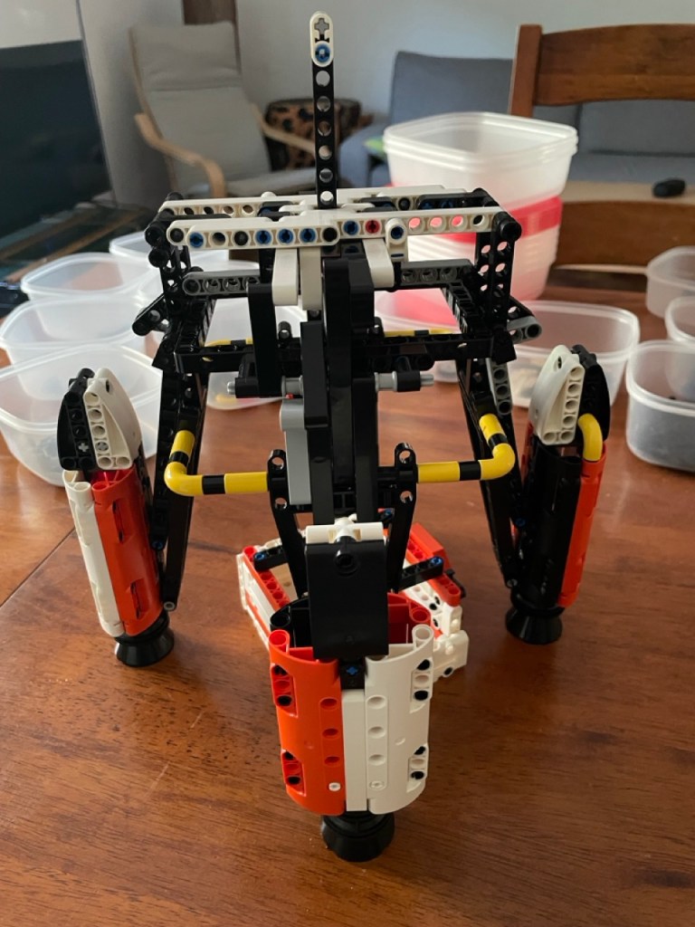
The white wings that were attached to the arms of the engine pods are missing. That needs some redesigning because of the grey 5×3 L-shaped bars that are now attached to those arms.
It starts to look like something, right? I definitely like the bigger engine pods. Their size in relation to the entire ship feels better. I have stopped calling it a sketch because the complexity and mass of the folding mechanism have fixed most of the sketch in place. Things will be added, but the square shape with four engine pods and the cargo bay in between is not going to change anymore. At least I think not.
That is it for now. With each post, I surprise myself with how much there is to show and explain. Let me know, please, if the read was worth your while. If you have any questions or comments, please drop them below or in Rebrickable or Reddit.
Frank van der Most, 23 June 2026
NAIP ( No AI involved production )
