MOC manual service. Get a step-by-step manual of your MOC.
Click here to learn more.
1 Recap
You can skip this if you have read the previous posts.
Mid May, I started making an alternative build ( alt build ) for the VTOL Heavy cargo spaceship LT81 ( in this post, I refer to it as the original set ), and I decided to explain how I think making an alt build starts. It maybe helpful for those who do not know how to start, and it helps me reflecting on how I work and hopefully improve, perhaps with your comments.
The posts are structured in chapters and sections in such a way that you can easily follow the steps and the thinking even if you are not interested in Technic or spaceships. The spaceship is just the example. You can read all about that in these five posts:
- Introduction to three steps
- Sketching a first design
- Running into a snag with an essential feature
- Pivoting
- Moving on after pivoting
At the end of the fifth post, I concluded, that ‘yes’, my idea will most probably fly.
Below you see the various overall sketch versions. To get to the last version, I had to do some rethinking of what I wanted to build, which essential features is has, and how the spaceship should be operating. I realized that one really needs flexibility in thinking.
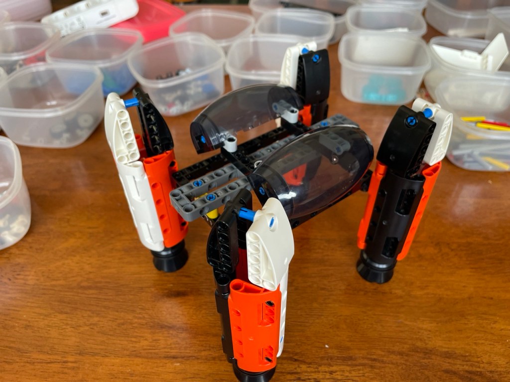
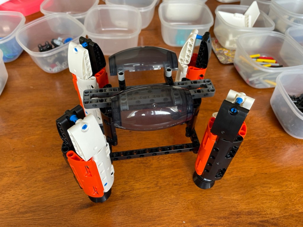
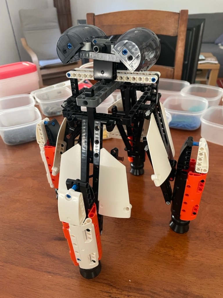
All images in this post can be clicked for a full screen version
After this rethinking, the idea for the spaceship is that 1) it has a more symmetrical and realistic design compared to the original set. Initially, I was toying around with both a three and four engine version, but I traveled down the four engine path. 2) Instead of hanging the cargo under the ship, it should be held inside the ship during flight. 3) The ship should have some folding mechanism for landing and takeoff, i.e. the engines have to move away from and back to the ship’s hull as illustrated in v3.
So, I finished the blog series of how to get started on an alternate build. Since there was quite some interest among Rebrickable and Reddit users, and because the writing keeps helping me improving my skills, I am continuing the series with some more insights and reflections on how I design MOCs and alternate builds.
2 About this post
Here is the link to the first post of that continued writing. At the end of that post, the spaceship looked like the image to the right.
The current post continues with more design insights.
As before, I aim to write in general about the design of an alternate build and use the spaceship as an example. If you are only interested in the design insights, then know that the following chapters have two sections. The chapter title announces the design insight, the A section tells about the development of the spaceship, and the B sections ( aptly called ‘MOC design’ ) provide the insights. Here is a clickable table of contents.
- 1 Recap
- 2 About this post
- 3 Overhaul instead of adding on
- 4 Overhaul leads to extra improvement
- 5 Zoom out and look at it from all sides
- 6 Rebuilding the MOC for the umpteenth time
- 7 Version 5
3 Overhaul instead of adding on
3A More power to the player
In the picture of version 4 of the spaceship, there is the ‘plunger’ in the middle. It is the vertical black bar with the short white bars attached to the top. Pushing it down, will make the arms with the engine pods fold out to the position that is shown in the picture. It works, but it has two disadvantages that make it cumbersome.
Firstly, it takes a lot of force to push the plunger down. My solution was to add a lever to make it easier to do. From here on, it will be called the plunger lever.
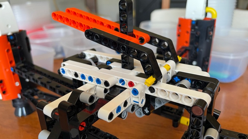
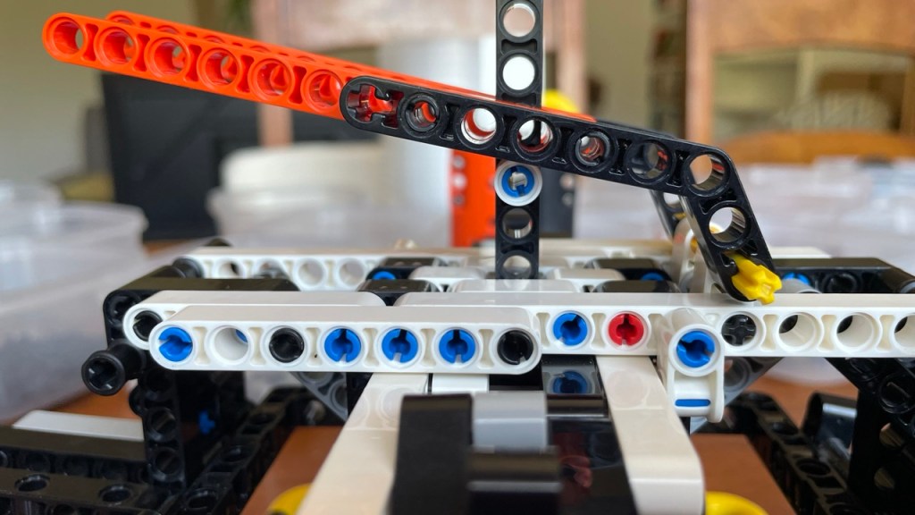
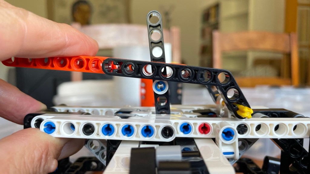
Secondly, the middle and right picture above illustrate that the plunger needs to be pushed down straight so that all arms move at the same time to the same position. If it doesn’t go down straight, it may even skip past the levers and loose it’s contact with their respective arms, which will then fall down. Getting the plunger and those arms back to their place is a bother and clearly the player should not have to do that. So, the plunger needed more guidance.
Below is the result of adding the guidance ( the light grey curved bricks ). With the horizontal orange and black bars, they are connected to plunger lever, so that they can bear the force exerted by the plunger lever and the plunger stick.
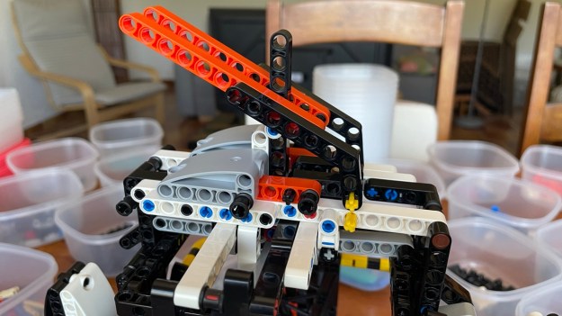
The plunger lever works. The guidance is a different story. It only works in one direction ( to the left in the picture above ). Fortunately, an unintended side effect of the plunger lever is that it also act as guidance because it pushes the plunger down on two sides of the plunger bar. This way, in total, three sides/arms are well guided. But the fourth is still a problem. As you can see in the pink oval in the picture below, the plunger stopped pushing down, and the light grey lever to it’s right skipped passed it. Compare with the grey lever directly left of the pink oval.
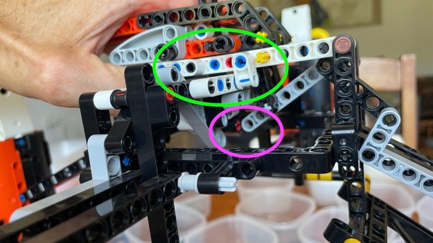
The green oval highlights how pushing the plunger lever down puts a lot of strain on the structure with the white bars that supports the plunger mechanism. The plunger lever works, but it still requires a lot of force to push it down.
My first inclination was to add more support to everything to make it all stronger. But, a little voice told me, “no, no more add-on’s”. The plunger lever and the guidance are add-on’s in themselves to solve a problem in the design. Adding more bricks to make everything stronger would be a second layer of add-on’s. It may be time to address the reason why pressing the plunger takes so much force.
3B MOC design
Adding more bricks to make something stronger often is a good idea. However, if and when you notice that you are about to repeat it once or twice to solve the same problem, then you should consider an overhaul.
For starters, adding more bricks costs more bricks. In a situation of a limited supply of bricks, it is not always the smartest move.
Secondly, adding more bricks, also makes the model more bulky, which often means that it becomes less pretty and less elegant to look at, and less fun to build.
Thirdly, add-ons to address design problems ( as opposed to adding features ) may be a matter of working on symptoms rather than problem’s causes. In some cases that is perfectly alright. It may do the job and it may be fast to implement. In other cases, for example when add-on’s are added to other add-on’s to address the same problem, an overhaul is the way to go: addressing the root cause(s) rather than the symptom.
4 Overhaul leads to extra improvement
4A A better lever system for the folding mechanism
Addressing the root cause of the problem, in this case boiled down to redesigning the basic folding mechanism. Remember, that it looked as follows:
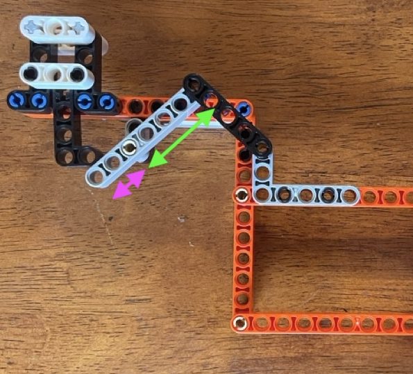
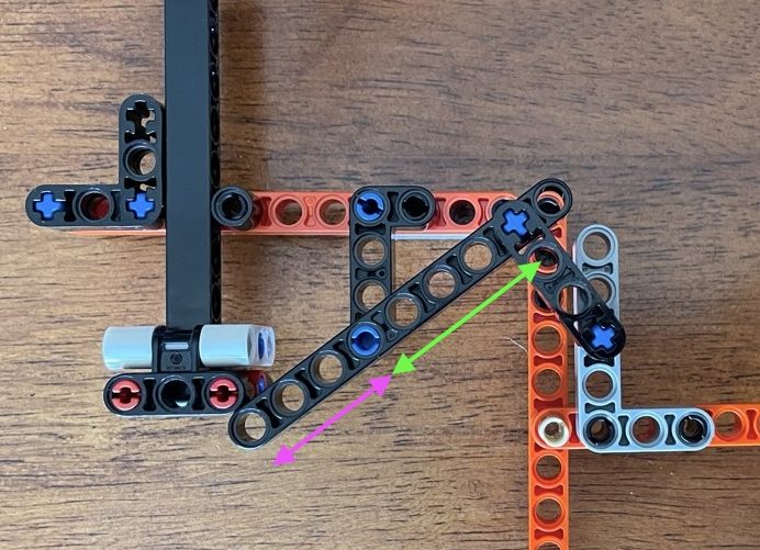
Notice that the leverage ratio is pink arrow length / green arrow length = 2/4 = 1/2 when measured from the centers of the pinholes. If one can change that ratio to a higher number, the force needed to push the plunger down would be smaller. Which means that it will be easier for the player and causing less strain on the support structure.
After some tryouts on the tinker frame, the best improvement that would allow the same range of movement that I could come up with was 3/5. It is only 0,2 times better than 1/2 but clearly noticeable.
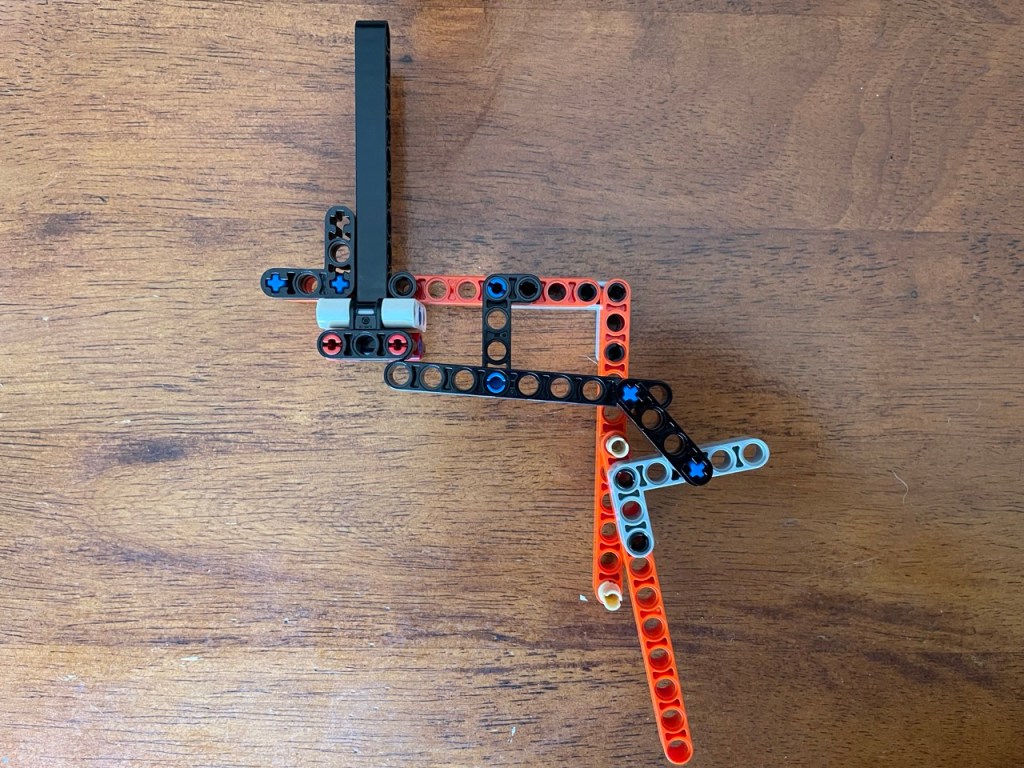
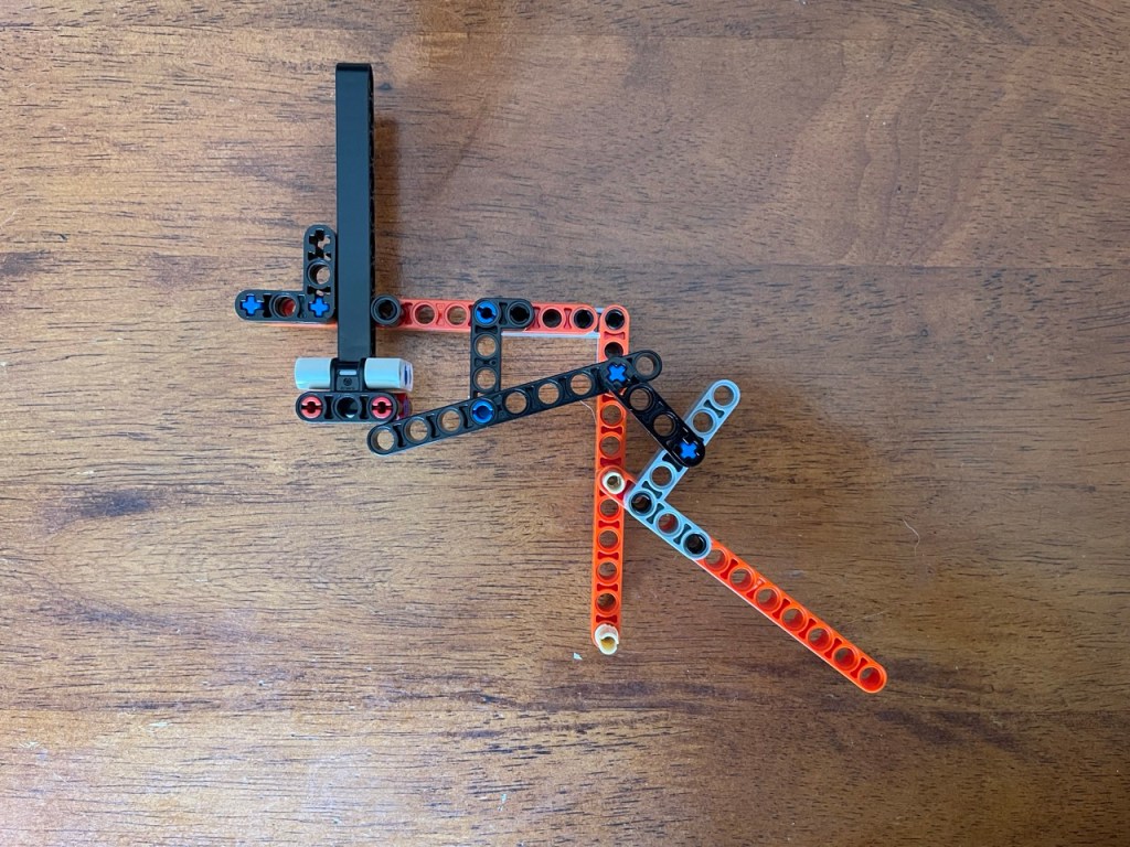
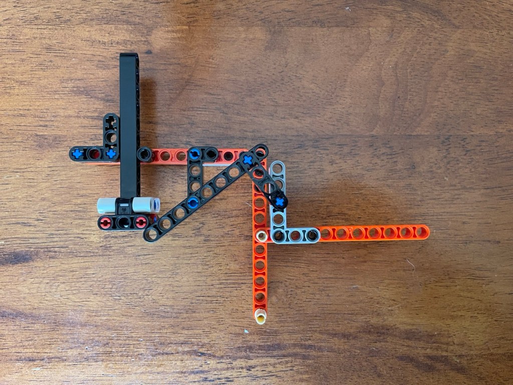
You may have noticed that the 4×2 L-shaped bar had to move one pin hole to the right. Also, the lever became one pin hole longer. Unfortunately, there is no 8 pin hole bar, so I had to use a 9 pin hole bar. This meant that the mechanism needs a different space to be able to move. Both changes together meant a complete overhaul of the support structure. In fact that overhaul had far more impact than the change of the lever system itself. This is a typical example of the cascade effect discussed in the previous post.
I had to rebuild the support structure from scratch, as illustrated by the following pictures
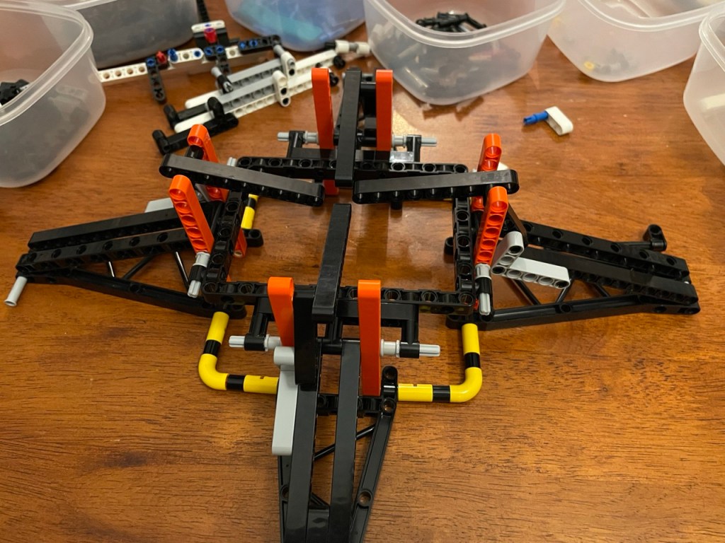
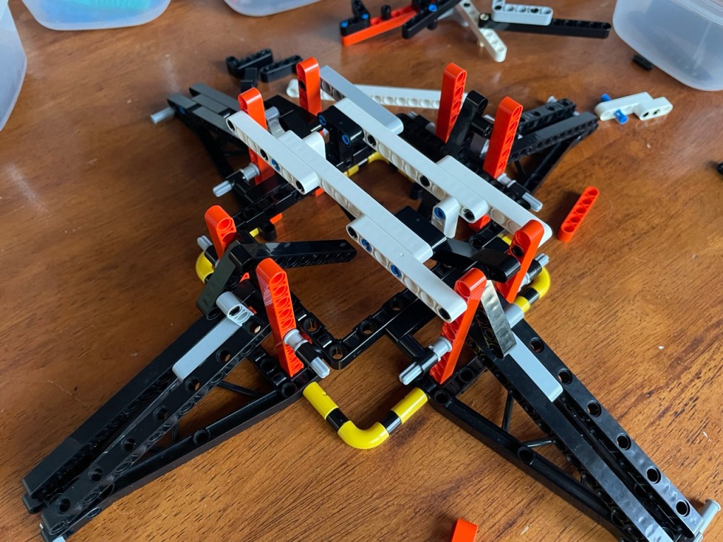
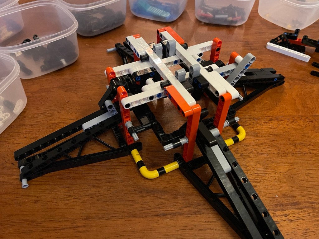
Notice how much simpler the new structure is compared to the previous one? The previous one is shown again to the right
4B MOC design
Overhauling a relatively big part of a design is a lot of work. More about that in the next chapter. One does an overhaul for a particular purpose, but it is an opportunity too for additional improvement. Probably, many bigger and smaller improvements can be made during the overhaul.
The single one reason for that is that the designer has a far better understanding of what at this later moment in the MOC’s development needs to be accomplished: what shapes it can and can not have, and how the parts or sub-models of a MOC connect to each other and to what is being overhauled.
Because the overhaul results in something simpler, it is likely to make more bricks available for use than there were before. Of course, some other bricks that previously were available may be needed for the overhaul, but the net effect is more likely to end up with more bricks rather than fewer. Put differently, if this is not the case, the overhaul may not be an improvement!
5 Zoom out and look at it from all sides
5A Looking for a solution
After the overhaul, the guidance of the plunger remained a problem for one of the arms. As the following picture shows, the plunger still skipped past one of the engine pod arms.
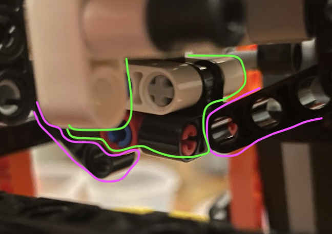
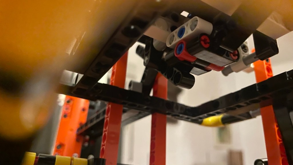
I tried out similar additions to what I had made before. Unfortunately, this still did not work, or not well enough. Then, more or less by accident, I turned the ship upside down. Which is something I should have done a long time ago. I had been trying to guide the plunger on the topside. I didn’t consider the bottom side because in my mental model of the model, there was no space left for additions to guide the plunger. Actually looking at the spot told me differently. And suddenly, I saw an easy solution. In the picture below you see the guidance outlined in pink and the plunger nicely stuck between them.
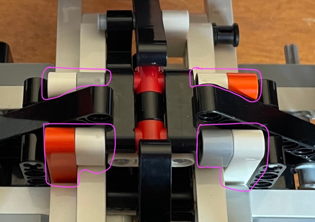
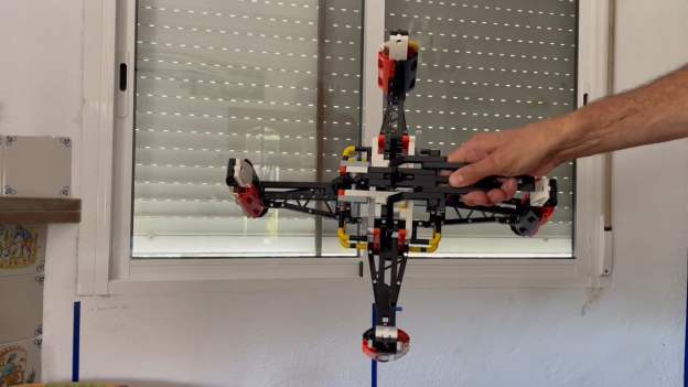
The new folding mechanism and the plunger guidance together work really well, as you can see in this video.
You may notice that the engine arm to the right is not lifting up as far as the rest. The reason for that is that the bottom of plunger is still pressed a little bit to the left when the plunger lever is pushed down. I decided to leave that as it is because I wanted to move on and I had exhausted my ideas to solve that problem.
5B MOC design
The design insight here is like kicking in an open door. But apparently, and if only for myself, I do need to add it. When solving a problem of a design, literally zoom out, and look at it from all angles. And look at it for real, not just at your mental model of the MOC.
5C MOC design – bonus
The video also shows that I again added a handle to hold the spaceship. About this handle, I have to admit some of defeat. I set out and managed to have the cargo inside the spaceship, instead of underneath it as in the original model.
What I did not think through though, is that in the original model the potential cargo space inside the spaceship was used for the handle. When I made my list of essential features, I did not ( consciously ) think of the handle. Now, I have to build it as an add-on. Perhaps it is a downside of the design approach that I am using of making rough sketches and going step by step, feature by feature, instead of planning everything from the start. But perhaps I should have defined it as an additional essential feature.
If I had done that, I would have taken it into account from the start. Perhaps already gave it a place in the first sketches. I did not do this, and this is the price that I pay: an ugly handle that really looks like an add-on. It would be great to find a way to integrate it better, or somehow hide it, that is, make it look less like a handle and an add-on.
6 Rebuilding the MOC for the umpteenth time
6A Taking it apart, change a thing, rebuilding it again
Here are two pictures of situations where I had to take the ship half apart for the next feature or improvement. It happens a lot in the course of designing a MOC or alternate build. There are different reasons for it, as becomes clear in this series of posts, but the work has a point in itself.
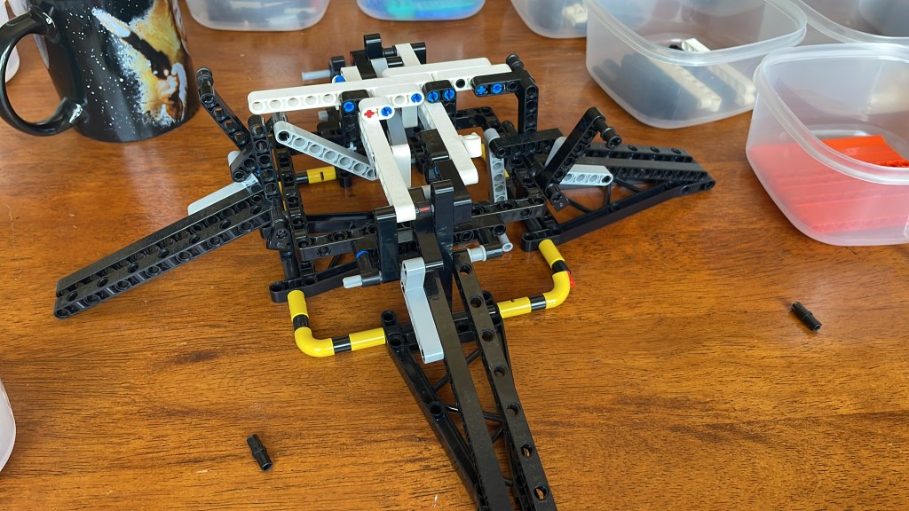
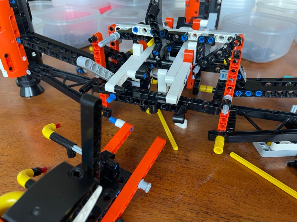
6B MOC design
Having to take apart and rebuild large parts of a MOC is tedious and sometimes difficult, but it has advantages.
Firstly, it teaches the designer a lot about how the current state of the model and helps finding simplifications and possible improvements.
Secondly, it shows the designer how complex the model has become, and thus what kind of skills the future builders of the model will have to have. It helps the designer to think about how best to build the model from scratch and set up the manual – assuming that there will be one.
It also seems there is a built-in rule going on: the more complex a (sub-)model is, the fewer ways exist to put it together, ultimately ending up in a model ( or sub-model ) that can only be built in one order.
7 Version 5
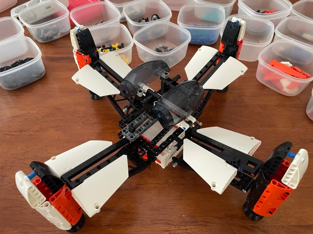
Here are a few pictures of version 5 with the new folding mechanism, and version 5.5 with the handle and the lever, and cockpits added.
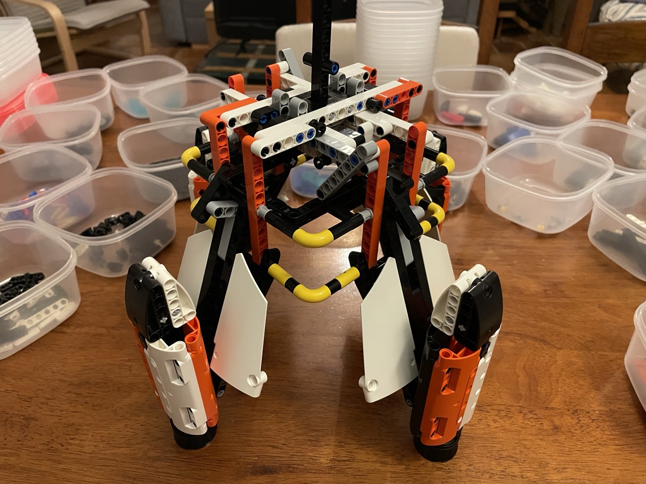
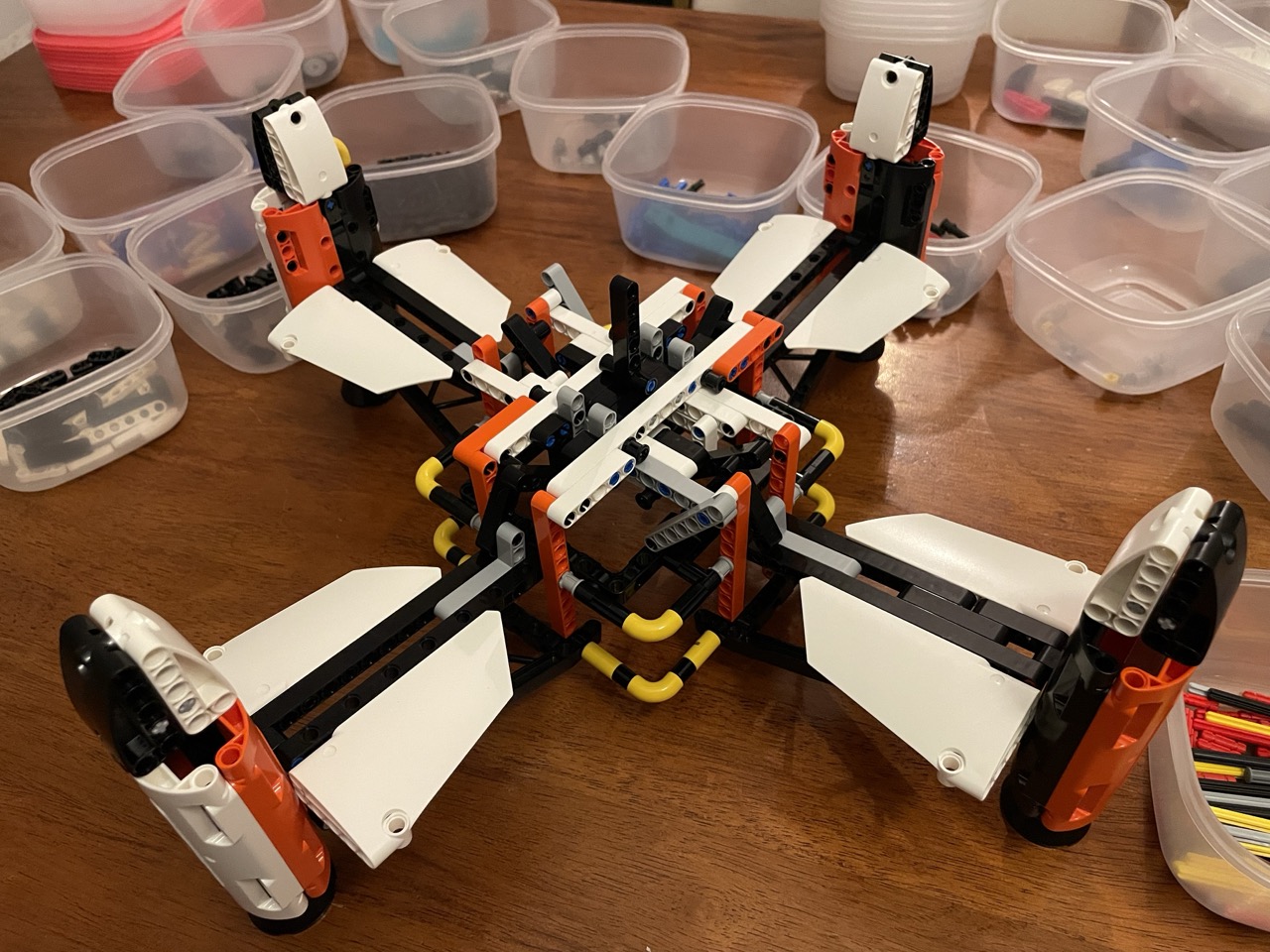
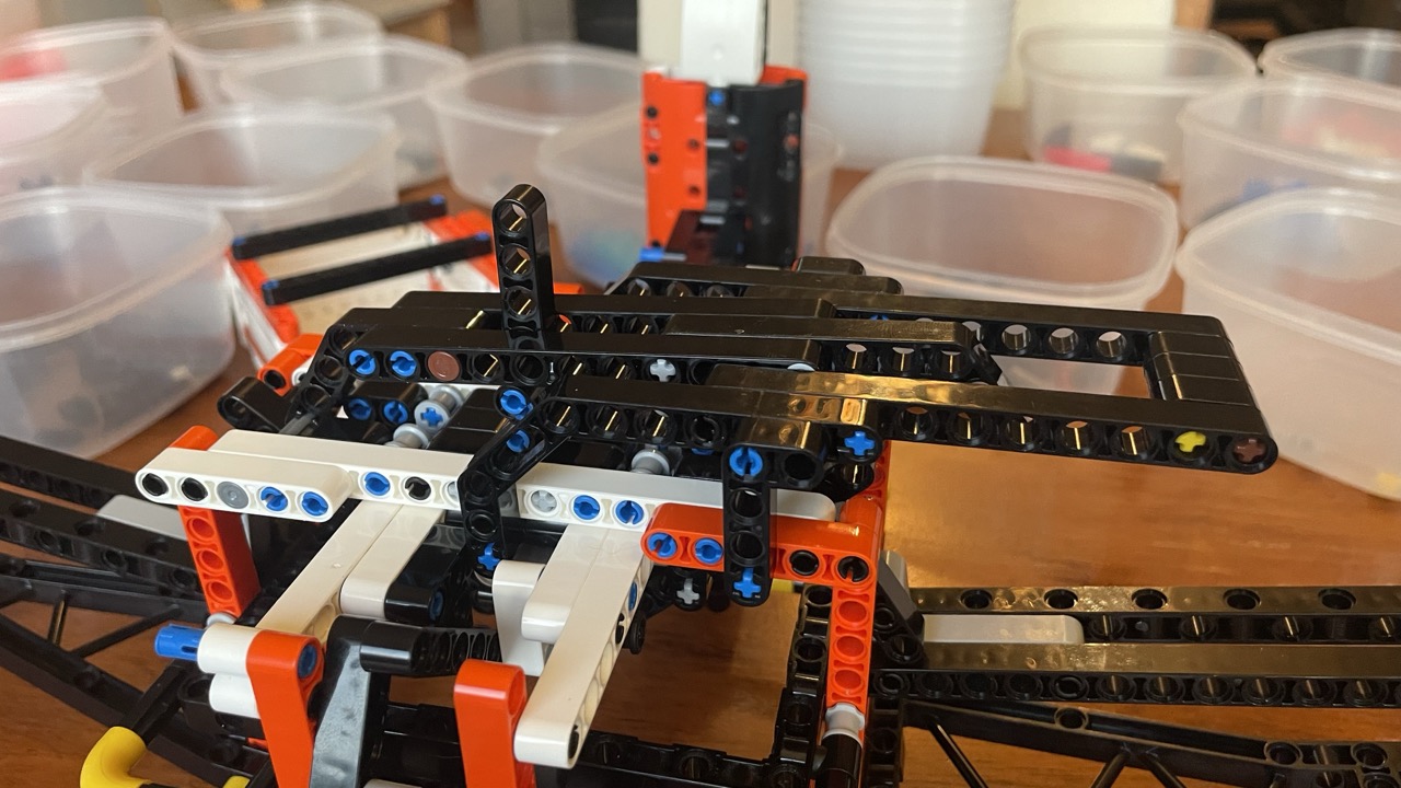
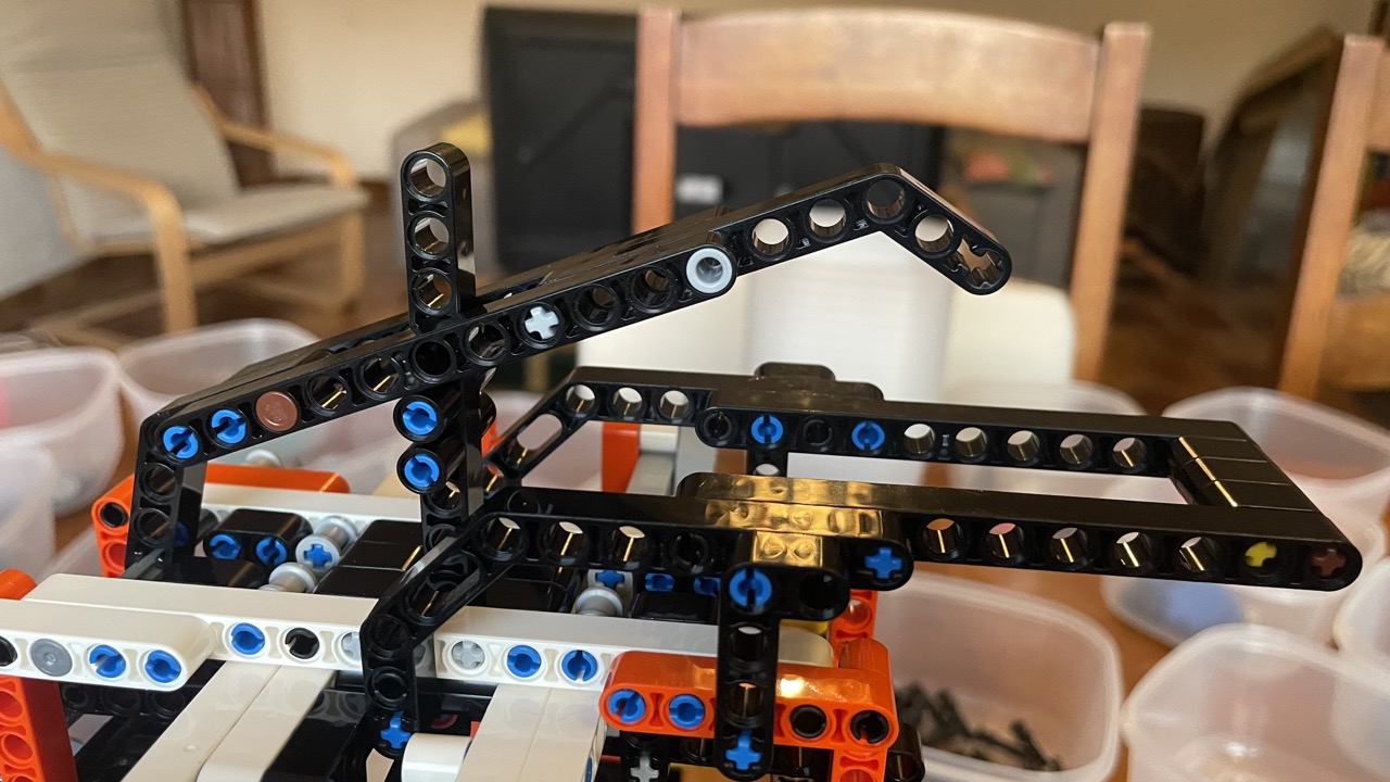
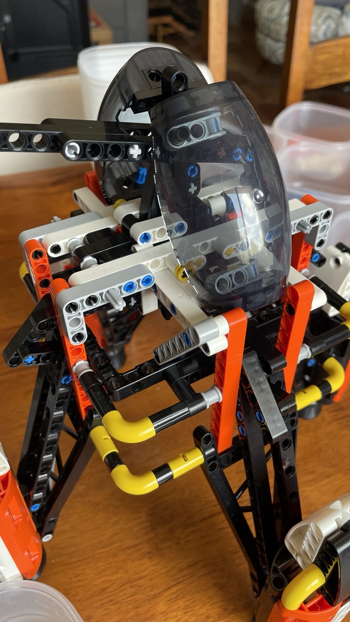
Now that the folding mechanism is done, the next important feature is a mechanism to hook, clamp or otherwise ‘grab’ the cargo container.
After that, I can focus on the ‘more is more’ phase of prettifying the MOC. For example I would like to somehow ‘hide’ the handle, as mentioned above. Also, from one of the early stages of the development, there is the idea to make the cockpits move together with the engine pod arms. Another ‘nice to have’ is something to keep the engine pod arms in their ‘down’ position. As the model is, it is only gravity that keeps them there, but that is little good for swooshing. What definitely needs attention is the overall looks of the ship. I am happy with the engine pods and the air brake wings on their arms, but the central part so far is just a rectangular box. Last but not least, the color scheme needs some more attention. I will see how far I get with these less essential features.
Frank van der Most, 28 July 2026
NAIP ( No AI involved production )

